|
|
|
Who's Online
There currently are 6043 guests online. |
|
Categories
|
|
Information
|
|
Featured Product
|
|
|
 |
|
|
There are currently no product reviews.
 ;
Good en helpfull black and white scanned Srfvice manual of the Philps D8444. Quick service and delivery
 ;
Scan was really good quality, easy to read, download easy
;
very good manual as always. easy to read, detailed and includes schematic
;
I'm very satisfied with your manual service. Your website made it easy to locate the correct manual. Also the quality is great and I never had a problem reading the fine details.
Thanks again.
Jeff Miller
JM Electronics
;
Good quality service manual German user manual. German user manual This is a quality scan of a manual in excellent condition and is just as good as having the original manual in hand
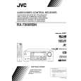
RX-7000RBK
Disassembly method
Removing the top cover (See Fig.1)
1. Remove the four screws A attaching the top cover on both sides of the body. 2. Remove the three screws B on the back of the body. 3. Remove the top cover from behind in the direction of the arrow while pulling both sides outward.
Top cover
B
A
2
A
2
Fig.1
C
Removing the front panel assembly (See Fig.2 and 3)
Prior to performing the following procedure, remove the top cover. 1. Disconnect the card wire from connector CN400 on the main board and CN402 on the power supply board in the front panel assembly. 2. Cut off the tie band fixing the harness. 3. Disconnect the harness from connector CN202 on the video board. 4. Remove the three screws C panel assembly. attaching the front
Video board CN202 Main board CN400
Front panel assembly
C
Tie band
Power supply board CN402
Fig.2
Front panel assembly
5. Remove the five screws D attaching the front panel assembly on the bottom of the body. Detach the front panel assembly toward the front.
D
D
Removing the rear panel (See Fig.4)
Prior to performing the following procedure, remove the top cover. 1. Remove the power cord stopper from the rear panel by moving it in the direction of the arrow. 2. Remove the twenty-six screws E attaching the each boards to the rear panel on the back of the body. 3. Remove the three screws F attaching the rear panel on the back of the body. Fig.3
E E E E
3 3
3
E
3
E
E
5
E
2
Cord stopper
F F
Rear panel
F
Fig.4
E
E
1-3
|
|
|
> |
|